| Author |
 Topic Topic  |
|
|
usb

138 Posts |
 Posted - 06/02/2005 : 15:23:17 Posted - 06/02/2005 : 15:23:17


|
-Confirm your LPT port BIOS setting is EEP mode.
-Makesure the jumper J3 (at the left side of DIP) is shorted the lower two pins. This jumper is switching betwteen the Vpp and A18.
Test all test points on this picture:
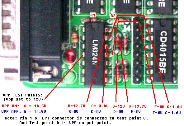
The point C should higher than G when Vpp is ON.
To test it, use Test H/W page in software, check and uncheck the Vpp pin1 checkbox in the software, and then measure the all the point voltage.
If your point C voltage is changing when you check-uncheck the Vpp pin 1, then your connection to PC is OK. (The voltage changing must be betwwn 0V and 3.5V above) Otherwise check the connection and the PC LPT port. The point C is directly connected to data cable Pin 1, so, you also can unplug the data cable form the programmer and measure the pin 1 of data cable to confirm the cable is OK. |
Edited by - usb on 08/31/2005 23:04:35
|
|
| Reply #1
ZLM

2937 Posts |
Posted - 09/02/2005 : 16:11:10
|
My Enhanced Programmer has no Red Vpp when doing writing. I am measuring from the listed pins to Ground, the measurements are as follows:
VPP ON A=14.24V B=0V C=1.57V D=0V E=0V F=0V G=1.63V
VPP OFF A=14.24V B=0V C=0V D=0V E=0V F=0V G=1.63V
So, what's wrong? |
 |
|
| Reply #2
usb
138 Posts |
Posted - 09/02/2005 : 16:13:27
|
It seems your LPT port pin 1 does not provide enough DC current. This
happend on some PCs. Most of PC will solve this issue by changing the PC
BIOS Setting of LPT Mode.
The Point C indicate the DC voltage from LPT port pin 1. To turn on the
Vpp, the point C need to be higher than point G=1.63V.
Your PC only output 1.57V. It just little bit lower than 1.63V.
If the problem still exist after you changed the LPT mode in BIOS. Then
there are couple of ways to solve this issue:
1. Solder a 1K resistor parallel with R1 (See thread picture).OR replace it by a about 500 ohm resister.
2.Replace the R2 with a 4.7K or 5K resistor.
|
Edited by - usb on 09/05/2005 21:41:04 |
|
|
| Reply #3
lewinskys

Canada
4 Posts |
Posted - 12/22/2005 : 17:31:11
|
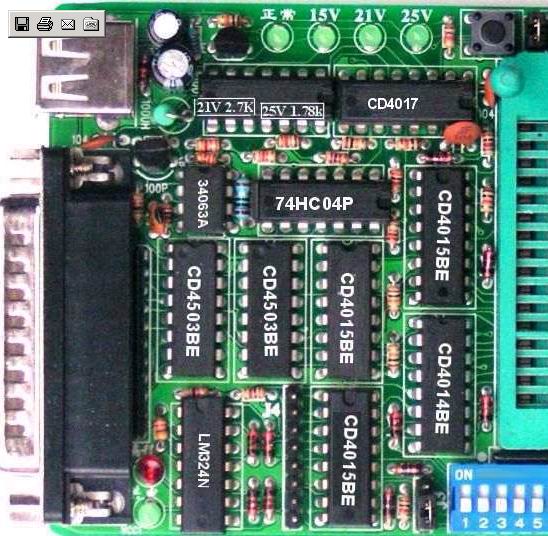
| USB... Can you post the full picture of that board with all the parts labeled? It would be very handy |
|
|
| Reply #4
usb
138 Posts |
Posted - 01/12/2006 : 23:24:28
|
I only have one half.
 |
Edited by - usb on 01/12/2006 23:30:29 |
|
|
| Reply #5
YMasquel
France
1 Posts |
Posted - 06/06/2006 : 15:11:51
|
Hello,
If that can help you here is the full refs of IC's.
Image Insert:
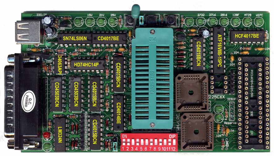
85.83 KB
Friendly, Yves. |
|
|
| Reply #6
ZLM
2937 Posts |
Posted - 06/07/2006 : 10:45:47
|
| Great! Many thanks. |
|
|
| |
Topic |
|