| T O P I C R E V I E W |
| Necrosaro420 |
Posted - 07/27/2013 : 23:09:27
Using new ADP-019 V4 adapter. Have J2 set to 29L, have J1 set to 29L3211, tried J3 on 3V as well as 5V. Chip seems to burn fine, but verifys fail. If you read the chip back, it is nothing even remotely close to what was burned onto it. The top if the actual file. The bottom is what is read after chip burns and fails verify.
Image Insert:
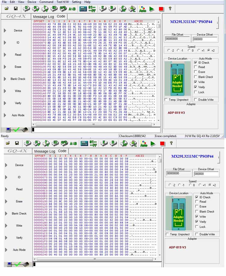
195.22 KB |
| 41 L A T E S T R E P L I E S (Newest First) |
| anniel |
Posted - 02/14/2020 : 09:03:41
quote:
Originally posted by fatherted
Just an update for anyone else still watching this and might find this useful:
The original resistor was rated for 2.2k but was actually 1.9K
I wired up a 680Ohm instead and the 100nF cap on the underside of the board on the VCC and Ground pins.
The verify got much farther, it would usually fail around 15-30 and was hitting 68% almost every time after those mods.
I was verifying and writing at max speed (+2). I changed this down to +1 and it worked!
I figure I might be able to play around with the resistor values if I need +2, but this is good enough for me.
Thank you for the follow-up. |
| fatherted |
Posted - 02/14/2020 : 08:38:45
Just an update for anyone else still watching this and might find this useful:
The original resistor was rated for 2.2k but was actually 1.9K
I wired up a 680Ohm instead and the 100nF cap on the underside of the board on the VCC and Ground pins.
The verify got much farther, it would usually fail around 15-30 and was hitting 68% almost every time after those mods.
I was verifying and writing at max speed (+2). I changed this down to +1 and it worked!
I figure I might be able to play around with the resistor values if I need +2, but this is good enough for me. |
| anniel |
Posted - 02/13/2020 : 15:07:09
quote:
Originally posted by fatherted
quote:
Originally posted by anniel
quote:
Originally posted by fatherted
quote:
Originally posted by RedScorpion
Hi Piko,
after hours i found the issue. Solder a 100nF capacitor between VCC and GND on the bottom side of adapter try again the chip.
With this my chips verified to 100%. I had contact Bad_Ad84 from assemblergames and he said the same.
Thanks
red
I was also wondering where to solder on this cap? Is there a good spot on the bottom of the board? I think I have found VCC and ground but just want to be sure - could someone advise as this would really help me out.
Also just ordered in some 1K resistors since I noticed I have the 2.2K resistor and some people noted that dropping this value helped.
Thanks in advance,
23 and 32.
Dude you rock thanks
You're welcome. |
| fatherted |
Posted - 02/13/2020 : 15:02:05
quote:
Originally posted by anniel
quote:
Originally posted by fatherted
quote:
Originally posted by RedScorpion
Hi Piko,
after hours i found the issue. Solder a 100nF capacitor between VCC and GND on the bottom side of adapter try again the chip.
With this my chips verified to 100%. I had contact Bad_Ad84 from assemblergames and he said the same.
Thanks
red
I was also wondering where to solder on this cap? Is there a good spot on the bottom of the board? I think I have found VCC and ground but just want to be sure - could someone advise as this would really help me out.
Also just ordered in some 1K resistors since I noticed I have the 2.2K resistor and some people noted that dropping this value helped.
Thanks in advance,
23 and 32.
Dude you rock thanks |
| anniel |
Posted - 02/13/2020 : 14:34:47
quote:
Originally posted by fatherted
quote:
Originally posted by RedScorpion
Hi Piko,
after hours i found the issue. Solder a 100nF capacitor between VCC and GND on the bottom side of adapter try again the chip.
With this my chips verified to 100%. I had contact Bad_Ad84 from assemblergames and he said the same.
Thanks
red
I was also wondering where to solder on this cap? Is there a good spot on the bottom of the board? I think I have found VCC and ground but just want to be sure - could someone advise as this would really help me out.
Also just ordered in some 1K resistors since I noticed I have the 2.2K resistor and some people noted that dropping this value helped.
Thanks in advance,
23 and 32. |
| fatherted |
Posted - 02/13/2020 : 10:58:45
quote:
Originally posted by RedScorpion
Hi Piko,
after hours i found the issue. Solder a 100nF capacitor between VCC and GND on the bottom side of adapter try again the chip.
With this my chips verified to 100%. I had contact Bad_Ad84 from assemblergames and he said the same.
Thanks
red
I was also wondering where to solder on this cap? Is there a good spot on the bottom of the board? I think I have found VCC and ground but just want to be sure - could someone advise as this would really help me out.
Also just ordered in some 1K resistors since I noticed I have the 2.2K resistor and some people noted that dropping this value helped.
Thanks in advance,
|
| anniel |
Posted - 01/17/2018 : 12:33:17
quote:
Originally posted by darleiv
HI DANIEL. 113/5000
DO YOU ADVISE USING AN EXTERNAL 9 VOLTS SOURCE ??? I TESTED AT SPEED -2 AND GOT VERIFY BUT HEX CORRUPTED
WILL THE CHIP THAT SAID RUIMS? LOTS AND LUCK COMPARE? I HAD A PROBLEM LOOKING LIKE THE CAT28C64BP BECOME A LIFE AFTER GIVING ERASE A 20 TIME AND RULE DANNDO BURN SEVERAL TIMES AND THE 29L 2 GRAVRAM SO HERE 100% THE REST OF HEADACHE
quote:
Originally posted by anniel
quote:
Originally posted by darleiv
i want solution for 29L3211 verify error help me plz after many times and very eproms flash. all not work. it bad chip? or adp 019 v4,1 not work
Some chips seem fine and others seem to need out of spec. voltage, did you try another source for the chips or different resistors?
No, tweaking the device definition line.
What do you mean "HEX CORRUPTED" ? |
| darleiv |
Posted - 01/17/2018 : 11:23:10
HI DANIEL. 113/5000
DO YOU ADVISE USING AN EXTERNAL 9 VOLTS SOURCE ??? I TESTED AT SPEED -2 AND GOT VERIFY BUT HEX CORRUPTED
WILL THE CHIP THAT SAID RUIMS? LOTS AND LUCK COMPARE? I HAD A PROBLEM LOOKING LIKE THE CAT28C64BP BECOME A LIFE AFTER GIVING ERASE A 20 TIME AND RULE DANNDO BURN SEVERAL TIMES AND THE 29L 2 GRAVRAM SO HERE 100% THE REST OF HEADACHE
quote:
Originally posted by anniel
quote:
Originally posted by darleiv
i want solution for 29L3211 verify error help me plz after many times and very eproms flash. all not work. it bad chip? or adp 019 v4,1 not work
Some chips seem fine and others seem to need out of spec. voltage, did you try another source for the chips or different resistors?
|
| anniel |
Posted - 01/16/2018 : 04:09:53
quote:
Originally posted by darleiv
i want solution for 29L3211 verify error help me plz after many times and very eproms flash. all not work. it bad chip? or adp 019 v4,1 not work
Some chips seem fine and others seem to need out of spec. voltage, did you try another source for the chips or different resistors? |
| darleiv |
Posted - 01/15/2018 : 23:00:21
i want solution for 29L3211 verify error help me plz after many times and very eproms flash. all not work. it bad chip? or adp 019 v4,1 not work |
| Ice Man |
Posted - 05/12/2017 : 07:15:25
I'm using ADP-019 V4.1 and I have never had problems with MX29L3211 yet.
However, when do we get support for MX29F1610? |
| anniel |
Posted - 04/23/2017 : 12:41:07
Ali chips maybe? |
| ZLM |
Posted - 04/23/2017 : 12:12:25
I think the problem is not the adapter. It is chip related. Most of chip work but some others need a higher voltage rating than its specification. |
| anniel |
Posted - 04/23/2017 : 05:09:38
make that 820ohm and 597ohm since the omega symbol appears as a �. |
| anniel |
Posted - 04/23/2017 : 05:02:42
You do know that if you put the 2.2k and a 1k resistor in parallel you get close to 680 ohm (687.5) or 2.2k and 820� gets you around 597�. |
| mamejay |
Posted - 04/22/2017 : 17:01:10
quote:
Originally posted by anniel
Did you try a 680 ohm resistor?
I am using a 820ohm as thats all I had on hand. After a few more attempts I had 3 successful writes.
This is so unreliable. Very disappointing. |
| anniel |
Posted - 04/22/2017 : 05:10:22
Did you try a 680 ohm resistor? |
| mamejay |
Posted - 04/21/2017 : 17:14:59
Bringing this thread back to life. I am so frustrated with this adapter. Has been working fine for some time but now I am getting verify errors. Always the last bit of data which is 00 writes as FF
I have changed the resister to 1k and added the cap but still same issue. Why is this happening? I have tried new cables, running external power and even trying slightly different values for the resistor. Same result every time. There must be a solution that works 100% of the time. Really has been issues since I got this setup |
| Bastian |
Posted - 07/29/2016 : 03:16:44
Great, thanks for the Information! :) |
| ZLM |
Posted - 07/23/2016 : 18:35:35
That is OK, as long as it can be verified. Thar 680 ohm resistor only cross the chip VCC and GND pin, lower value only use more power from programmer. |
| Bastian |
Posted - 07/22/2016 : 17:39:26
Hi everyone,
I found this thread because I am encountering similar problems.
I have the new? adapter ADP-019 V4.1 which has already a 1k resistor instead of the 2.2k resistor.
But my problems were more serious. It seems that the chip is written incorrectly because it wasn't readable in the device i put it in after flashing.
Then I replaced the 1k resistor with a 2.2k resistor and still got the verify error message, but my chip was readable in my device without any problems.
Now I changed the resistor to a 680 ohms resistor.
With this the verify process ends without errors.
Now my question: Is it bad to put the 680 ohms resistor in this adapter or is it okay to flash my chips on this way?
Would be great to get an answer, thanks! :)
|
| Jarryson |
Posted - 05/27/2016 : 16:16:14
I have this adapter (chinese) in my GQ 4X, 0 problems with MX29L3211. My adapter has a 2.2K resistor. |
| MaarioS |
Posted - 12/10/2015 : 06:22:28
The same exact issues here. I get verify fail of MX29L3211 always at random moments.... So, what is the solution to that?? Change resistor or cap?? |
| ZLM |
Posted - 08/14/2015 : 11:34:18
No. It is 2.2k on board. It located at the lower right side of ZIF socket. |
| zzattack |
Posted - 08/08/2015 : 03:01:40
Same issue with v4.1 adapter. Adding 100nF cap doesn't help. There's two 56 ohm resistors and one 10k resistor. Should I try replacing the 10k for 1k?
Verify Failed, Address=0x2FFFFF, Device=0xFF, Buffer=0x00
Address is always 0x2FFFFF. |
| nihonsx5 |
Posted - 12/21/2013 : 00:15:56
Hi, I changed the 2.2K resistor for a 1K. It worked !! :)
Thank you for help ! |
| ZLM |
Posted - 12/14/2013 : 22:26:09
There is 2.2k resistor on the adapter, change it to 1K? |
| nihonsx5 |
Posted - 12/13/2013 : 14:45:15
Hi, same issue with V4 adapter. Is there a solution ? Change resistor ? Add a capacitor ?
For capacitor, where I add this capacitor exactly ?
Thank you. |
| ZLM |
Posted - 10/22/2013 : 18:51:27
In this case,it is verify problem, not the writting. May need lower the 2.2k resistor value. |
| Necrosaro420 |
Posted - 10/22/2013 : 12:28:54
I have found that even if it does not verify all the way, the chip still is burned properly. |
| Jon2887 |
Posted - 10/21/2013 : 15:17:58
Where exactly did you solder the capacitor on the adapter? I am having a failing verify in the 90% range. |
| Bad_Ad84 |
Posted - 09/25/2013 : 12:12:21
This is recommended in most datasheets of the chips. Should really be on the adapter(s) anyway. |
| ZLM |
Posted - 09/19/2013 : 00:11:01
Thank you for your information.
can you post a picture of your mod?
There is 2.2k resistor on the adapter, can you parallel the cap on it? |
| RedScorpion |
Posted - 09/16/2013 : 09:42:03
Hi Piko,
after hours i found the issue. Solder a 100nF capacitor between VCC and GND on the bottom side of adapter try again the chip.
With this my chips verified to 100%. I had contact Bad_Ad84 from assemblergames and he said the same.
Thanks
red |
| Pikointeractive |
Posted - 09/15/2013 : 19:45:33
Same issues here, I sometimes can get it to burn 100% choosing the MX29L320CT or CB but 1 out 6 chips works. |
| RedScorpion |
Posted - 09/14/2013 : 08:57:30
Same issue here. V4 adapter is used and verified fails at 98%. Resolder all connections -> same issue.
If read back the content, 2-3 bytes are different... If i write up to 3,5 mb it works well.
The adapter and programmer was very expensive and 3 of 4 chips has problems with adapter or epromer... This is not satisfying for me...
150$ epromer + 150$ for TSOP, 27C322 and PSOP44 adapter and a only programming issues... The V4 was designed to programm the 29L3211 chip! Has nobody test the chip with 4 Mb files?!
The old willem for lpt works fine for 10 years and more... ;/
Any suggestions what the problem is?!
|
| Necrosaro420 |
Posted - 07/29/2013 : 20:29:41
Seemed to work, except it fails verify around 98%. I get alot of chips that do that though and work fine. Good eye there. Thanks! |
| Necrosaro420 |
Posted - 07/29/2013 : 20:15:03
Ahhh damn, your right. I even looked at jumpers to make sure they were correct at least 10 times lol. |
| ZLM |
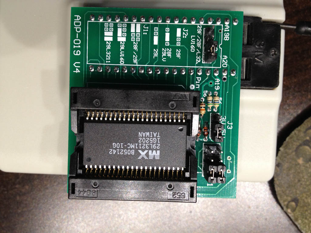
Posted - 07/29/2013 : 20:04:58
J1 wrong. It should be two vertical pins connected. Two jumpers should look like || |
| Necrosaro420 |
Posted - 07/28/2013 : 01:17:01
nope, still looks like the bottom picture when I read it. I just the the adapter in the mail today too. Also tried resetting the chip several times.
Image Insert:
158.78 KB |
| ZLM |
Posted - 07/27/2013 : 23:32:51
J3 on 5V.
I think some pins may have contacting problem.
Try to cancel the writing when it goes to 1%, and then read the chip to see if the address 00000 section can be written correctly.
|