| Author |
 Topic Topic  |
|
|
Praz

22 Posts |
 Posted - 08/25/2008 : 18:11:09 Posted - 08/25/2008 : 18:11:09


|
Is the GQ-3X capable of programming the SST25VF080B?
Thanks |
|
| Reply #1
ZLM

2949 Posts |
Posted - 08/25/2008 : 20:44:22
|
see: http://www.mcumall.com/forum/topic.asp?TOPIC_ID=1433
GQ-3X current software(Re.3.01) official support list does not include SST25VF080B. It is only included in the GQ-4X supported list.
However, the GQ-3X still be able to support sst25vf080b. But it only supports very slow mode on this chip. You can add this chip youself if you want.
For testing, try to add this line to devices.txt:
Name="SST25VF080B(Slow mode)",ID="BF8E",Class="SST25VF020",CodeSize="1048576",VCC="3.6V",Category="SERIAL_EPROM",MFG="SST",Speed="1",Message="To get fast operation, please upgrade to GQ-4X"; |
 |
|
| Reply #2
ZLM
2949 Posts |
Posted - 08/26/2008 : 01:43:32
|
To do this, should download Re3.01B and later version software.
For SST25VF040B:
Name="SST25VF040B(Slow mode)",ID="BF8D",Class="SST25VF020",CodeSize="524288",VCC="3.6V",Category="SERIAL_EPROM",MFG="SST",Speed="1",Message="To get fast operation, please upgrade to GQ-4X"; |
|
|
| Reply #3
Praz
22 Posts |
Posted - 08/26/2008 : 15:48:36
|
Thanks. I'll give this a go with the newest version of the software. Just one question. When selecting the SST25VF080B in the program it shows "No adapter required for DIP chip". The SST25VF080B is available as a SOIC or WSON only so cannot be plugged into the programmer. Just want to make sure we are both referring to the same chip.
http://www.sst.com/products.xhtml/serial_flash/25/3.0V/SST25VF080B
Thanks again
John |
|
|
| Reply #4
ZLM
2949 Posts |
Posted - 08/26/2008 : 18:54:59
|
Yes. It is referring same chip. The adapter info will be added on GQ-4X. For your GQ-3X, you can use following line:
Name="SST25VF080B(Slow mode)",ID="BF8E",Class="SST25VF020",CodeSize="1048576",VCC="3.6V",Category="SERIAL_EPROM",MFG="SST",Speed="1",Adapter="SOIC8-DIP or WSON8-DIP adapter",Message="To get fast operation, please upgrade to GQ-4X"; |
|
|
| Reply #5
Praz
22 Posts |
Posted - 08/27/2008 : 07:57:08
|
Thanks for the reply. The board the chip is on has a header to access it. As soon as I finish the wiring harness to go from the programmer to the header I'll post up the results.
John |
|
|
| Reply #6
Praz
22 Posts |
Posted - 08/27/2008 : 19:55:25
|
| Using the above string I am able to ID, read, erase and blank check the chip. The programmer fully writes to the chip but fails on verify. Takes approximately 9 minutes to read and 1 hour to program the chip. |
Edited by - Praz on 08/27/2008 20:02:09 |
|
|
| Reply #7
ZLM
2949 Posts |
Posted - 08/28/2008 : 00:19:07
|
what is the address of verify fail?
Do you know the read if correct?
Are you doing in circuit programming no a motherboard? If so, did you power up the motherboard? |
|
|
| Reply #8
Praz
22 Posts |
Posted - 08/28/2008 : 03:32:56
|
The chip is on a motherboard with all power removed while programming. After the write the board will not boot.
The address of the verify fail is different each time the chip is written to. Looking at the code memory there is random data scattered at different addresses compared to the original file.
I filled the buffer with FFh and am currently writing to the chip. I'll check in an hour or so to see if any random data has been written. Then I'll pull another board and read that chip and compare to the original file. |
Edited by - Praz on 08/28/2008 04:50:52 |
|
|
| Reply #9
ZLM
2949 Posts |
Posted - 08/28/2008 : 07:51:32
|
What is your programmer hardware version?
How long is your wires to motherboard?
It seems the signal quality is poor.
The testing trick is to write about 1% then press stop, do a verify see if the first 1% been verified. This will save your trying time.
Also, make sure the speed is at slowest -2 position.
Try to not connect the power wire(pin 8), and use motherboard power. See if this make differences. |
|
|
| Reply #10
Praz
22 Posts |
Posted - 08/28/2008 : 09:01:08
|
Programmer revision is 1.20.
From the programmer to the motherboard is approximately 24".
I just wrote 3% to the chip. The beginning of the code verified. I read it back and compared it to the file code and the first portion also matched. This is the strange part. Allowing the the chip to be partially written to results in valid code. After completing a complete write cycle there will be random data in the beginning of the code.
The speed is set to -2.
I'll try disconnecting the power wire and using board standby power. I tried standby power with power at pin8 also and the chip cannot be ID'd. |
|
|
| Reply #11
ZLM
2949 Posts |
|
| Reply #12
Praz
22 Posts |
Posted - 08/28/2008 : 11:03:06
|
Will do in just a couple of hours.
Thanks |
|
|
| Reply #13
Praz
22 Posts |
Posted - 08/28/2008 : 13:37:17
|
| Testing the beta build now. Write from 0% to 25% in about 1 minute. From there on slows back down to approximately 1% per minute. I stopped the write at 10% and 30%. Both writes verified up to the address that was stopped at. Currently letting it program the full chip. If a full write still fails I might try 25% at a time using the offsets. |
Edited by - Praz on 08/28/2008 14:04:27 |
|
|
| Reply #14
Praz
22 Posts |
Posted - 08/28/2008 : 15:20:32
|
Happy update. Don't know what you did but the beta build did the trick. As wrote above the first 25% wrote in 1 minute. The next 75% took 65 minutes. But the end result was a successful write and that's what matters.
Would the ADP-056 JTAG/SPI in circuit programming adapter help in this situation?
Once again a big thanks for your help and support
John |
|
|
| Reply #15
ZLM
2949 Posts |
Posted - 08/28/2008 : 16:37:18
|
Thanks for the update.
The ADP-056 is designed for in-circuit-programming. Just like your situation. It will maintain a better signal quality and reduce the signal noise. It seems you do not need this in this particular case since you have programmed chip successfully. But you may need it on other brand/model motherboard.
The SPI speed on GQ-4X will be much faster. The write process speed on this chip is about 25-30 times faster.
By the way, may I know what is your motherboard brand/model?
|
|
|
| Reply #16
Praz
22 Posts |
Posted - 08/28/2008 : 17:04:21
|
The board is a DFI JR P45-T2RS. What most people will not understand is this was a brand new board not needing programming. I just received this and some other boards from DFI all with SPI soldered BIOS chips. As this is the direction the industry is heading I thought now would be a good time to get the programmer sorted out should the need arise for it. I test boards for different manufacturers so it's not unusual to corrupt a BIOS now and then.
So instead of and hour the GQ-4X would do it in 4 or 5 minutes? Is so I may order it and the adapter. I already have a Dual Power Willem and have had this GQ-3X for only a few months so it's something to think about.
John
 |
|
|
| Reply #17
ZLM
2949 Posts |
Posted - 08/28/2008 : 20:07:17
|
Tested this SST25VF080B chip on GQ-4X Re3.02Beta2: Read: 2 minutes 20 seconds, Write: 2 minutes 46 seconds. Also, there are rooms for increasing speed in the future software release for GQ-4X.
|
|
|
| Reply #18
Praz
22 Posts |
Posted - 08/29/2008 : 07:30:16
|
Thanks for testing. Pretty convincing argument for upgrading the programmer.
John |
|
|
| Reply #19
Praz
22 Posts |
Posted - 08/29/2008 : 10:17:37
|
| One other question. What are the pinouts of the 8 pin connector on the ADP-056 as compared to the actual chip? |
|
|
| Reply #20
ZLM
2949 Posts |
Posted - 08/29/2008 : 14:11:22
|
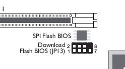
[b]Adapter SPI Pin out:[/b][br]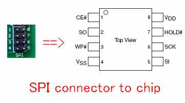 [br][size=1] 8.33 KB[/size=1] [br][size=1] 8.33 KB[/size=1] |
|
|
| Reply #21
Praz
22 Posts |
Posted - 08/30/2008 : 07:38:23
|
I have attached an image of the TOOL-009 DIP8 IC Simple programming/Testing Clip. What is the connector at the arrow? 1x8, dual 1x4 or a single 2x4 connector? I will have to adapt that part of the cable to the motherboard header.
Thanks
John
Image Insert:
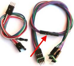
10.63 KB |
|
|
| Reply #22
ZLM
2949 Posts |
|
| Reply #23
Praz
22 Posts |
Posted - 08/30/2008 : 10:18:35
|
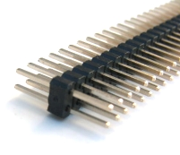
The boards have a 2x4 header for the programmer connection which is why I'm curious as to the type of connector the arrow is pointing to. Would save my some time rounding up connectors if that lead will work.
Image Insert:
7.34 KB |
|
|
| Reply #24
ZLM
2949 Posts |
|
| |
Topic |
|