| Author |
 Topic Topic  |
|
|
lando

France
18 Posts |
|
| Reply #1
ZLM

2949 Posts |
 Posted - 04/02/2007 : 13:28:47 Posted - 04/02/2007 : 13:28:47


|
It seems the chip is not in the correct position. Can you confirm your chip is in the right position?
Also, the DIP switch need to all OFF. |
 |
|
| Reply #2
lando
France
18 Posts |
Posted - 04/02/2007 : 13:50:13
|
can you confirm that the begin chips must be at 5 pins Up?
all switch are off there are no problem with this :) |
|
|
| Reply #3
ZLM
2949 Posts |
Posted - 04/02/2007 : 15:44:10
|
The chip's pin 1 should face ZIF handle. And the pin 1 should in ZIF's pin8.
chip's pin 4 should in ZIF's pin 11.
chip's pin 5 should in ZIF's pin 22. |
|
|
| Reply #4
lando
France
18 Posts |
Posted - 04/02/2007 : 16:40:44
|
Yes I agree With you... but it doesn't work :(
I have try with the HN27C256G, this is recognize 1 time of 2. |
|
|
| Reply #5
ZLM
2949 Posts |
Posted - 04/02/2007 : 20:27:12
|
I'll get my 12F629 tomorrow, so that I can test it out.
You may need to check if your HN27C256G has clean pins. This will help to get correct ID.
|
|
|
| Reply #6
lando
France
18 Posts |
Posted - 04/03/2007 : 03:05:28
|
Thanks for your fast support. I hope you can find the problem (maybe it's chair-keyboard interface)
other question :
do you think you add support of Pic16F745 & Pic16F765?
|
|
|
| Reply #7
ZLM
2949 Posts |
Posted - 04/03/2007 : 20:17:08
|
Tested 12F629. There is a software bug on this chip. It should be fixed soon.
For now, it will work through ICSP header. But you need modify the device.txt: remove the Package="DIP8" in the 12F629 config line. In this case the chip location picture will show a 18 pin chip. Just ignore the picture since you are using ICSP header only. |
|
|
| Reply #8
ZLM
2949 Posts |
Posted - 04/04/2007 : 00:05:15
|
| Please download R1.12A and try. IT should fix the 12F629 reading issue. |
|
|
| Reply #9
lando
France
18 Posts |
Posted - 04/04/2007 : 11:47:26
|
| thank you very much, great job. |
|
|
| Reply #10
lando
France
18 Posts |
Posted - 04/10/2007 : 05:20:17
|
Hello,
I have a problem with pic12F629,
I can Read devices and verify (and it's right).
But when i try to write on it : it make nothing.
the verify failed (because the device still blank)
It work sometimes and sometimes not... |
|
|
| Reply #11
ZLM
2949 Posts |
Posted - 04/10/2007 : 10:43:03
|
| Can you try slow down the speed? |
|
|
| Reply #12
lando
France
18 Posts |
Posted - 04/10/2007 : 10:47:33
|
I have try on another computer in many speed and many Chips (9)... and i have the same problem :
Many chips that I have write previously are blank or there are data but very instable (change sometimes...)
And i can't write on them |
|
|
| Reply #13
ZLM
2949 Posts |
|
| Reply #14
lando
France
18 Posts |
Posted - 04/10/2007 : 14:00:00
|
there are some progress....
I can erase the chips ..
but it only write the first word data... all still "3FFF" :) |
|
|
| Reply #15
ZLM
2949 Posts |
Posted - 04/10/2007 : 15:08:39
|
Can you try "-2" speed?
Are all chips same problem?
Does the ID work correctly?
I have three 12F629 and they all work fine on this version software. |
|
|
| Reply #16
lando
France
18 Posts |
Posted - 04/10/2007 : 22:53:01
|
I have try 2 chips in all speed
the ID work.
I will try others later
EDIT: I have try with a 9V power supply..
I work better (A big part of the chips is write) but I have many errors
Other questions : it would seem that I need to erase a chips before re-write on it, Am I wrong?
Can you says me if I need to write the "OSCCAL value" at the end of a .HEX? or if the programmer make it for me? |
Edited by - lando on 04/11/2007 14:31:19 |
|
|
| Reply #17
ZLM
2949 Posts |
Posted - 04/11/2007 : 17:28:27
|
Yes. Before write, you need to erase the chip and do a blank check.
The erase will erase the OSCCAL value too. The OSCCAL you need type in at the last byte buffer(at 3FF location).
|
|
|
| Reply #18
lando
France
18 Posts |
Posted - 04/11/2007 : 21:56:40
|
If I lose a OSCCAL Value... the chips is dead? or if I type a value near it can work? (the value is somethings like this 34**)
How you can simply know if a chips work or not? the program what I have is to heavy to know if it work or not (on a prototyping breadboard)
PS : can you make a popup to advice the user for OsCCAL change? |
Edited by - lando on 04/12/2007 06:59:07 |
|
|
| Reply #19
lando
France
18 Posts |
Posted - 04/12/2007 : 12:12:20
|
I have test with a 12V power supply and it write in all speed... but even if I make a blink led... it doesn't work :'(
i don't understand... |
Edited by - lando on 04/12/2007 12:12:42 |
|
|
| Reply #20
ZLM
2949 Posts |
Posted - 04/13/2007 : 07:42:09
|
If you only test the blink LED, then the chip will run if you do not have the OSCCAL value. Only the on chip OSC is not accurate.
The OSCCAL value only give you a accurate OSC frequency on chip. You can find a OSCCAL vaule youself if it is lost.
This chip does not need a 9V external power. You can use it anyway if you found it works better.
Please check the all CFG bit. Especially on the OSC source selection bits. If you config the chip wrong, then it will not work at all.
I'll post another version for testing later. |
|
|
| Reply #21
davbere

4 Posts |
Posted - 04/13/2007 : 18:36:08
|
The 1.12D worked for me.
Thankyou. |
|
|
| Reply #22
ZLM
2949 Posts |
|
| Reply #23
davbere
4 Posts |
Posted - 04/14/2007 : 21:36:26
|
| It now has the warning which is good, but after a omplete erase it asks if its ok to reprogram the origial value back. When I select yes it shows it programming but upon rereading the chip the original value was not restored. |
|
|
| Reply #24
ZLM
2949 Posts |
Posted - 04/15/2007 : 00:26:40
|
I tested it seems working.
Anyway, I need more info inorder to find out the problem:
1. How do you check the OSCCAL after an erase?
2. Press the CFG button, does the Direct Device Memory Access read/write are working?
3. Did you try solw down the speed to "-2"
4. Does the ID work?
For the new version software, the OSCCAL value will not accessible(both read and write) from the main code buffer.
Please download the R1.13 Beta again. This one added the verification process after OSCCAL been writen.
http://www.mcumall.com/download/TrueUSBWillem/TrueUSBWillemGQ-2X1.13BetaSetup.exe |
|
|
| Reply #25
lando
France
18 Posts |
Posted - 04/16/2007 : 13:43:04
|
Hello, I have received my new whips (with a good OSCCAL) and nothing work...
1 we can check OSCCAL when we clic on erase (before launch)
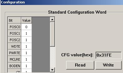
2 in CFG http://img362.imageshack.us/img362/6391/cfgaz6.png
3 all work (incl ID) with 12v, without it i only can write the first word in the chips
Do you have an HEX what work with your pic to test it with mine (a blink led or somethings like this) |
|
|
| Reply #26
ZLM
2949 Posts |
Posted - 04/16/2007 : 20:08:54
|
I found a blink LED hex file from internet
It uses internal oscillator. Output on pin 7. Connect a LED to VCC via a 330ohm resistor.
The hex file:
:020000040000FA
:020000000428D2
:08000800FF30A100FF30A2004F
:10001000211031200530142023142D200530142008
:1000200023102D200A281328A4002408A5006430DA
:10003000A6000A301B28A700FF30A8002608AA0047
:100040002508A9001730280703182328A90B222800
:10005000AA0B2028A70B1E2808002E28230885009D
:0A006000080032282108650008009E
:02400E0084111B
:00000001FF
slower version:
:020000040000FA
:020000000428D2
:08000800FF30A100FF30A2004F
:10001000211031201930142023142D2019301420E0
:1000200023102D200A281328A4002408A5006430DA
:10003000A60001301B28A700FF30A8002608AA0050
:100040002508A9001730280703182328A90B222800
:10005000AA0B2028A70B1E2808002E28230885009D
:0A006000080032282108650008009E
:02400E0084111B
:00000001FF
It not working good. I only can get LED blinking when I touch the pin 2 using my hand finger.
The CFG bit is:
15.71�KB |
|
|
| Reply #27
lando
France
18 Posts |
Posted - 04/17/2007 : 00:26:12
|
If I test with CFG 0x3184... I can't write anythings and the ID doesn't work
now my CFG is block on 0x3180.. If I test to write an other value, it doesn't work.
Other things : Th CFG configuration isn't in HEX? CFG will be modified when I load an HEX no?
EDIT : My configuration must be like in this picture when I load my HEX http://www.xavboxwii.com/photos/wiifree/wiifree-06.jpg
There ii no way for true usb to be support in WinPIC, or other software like this? |
Edited by - lando on 04/17/2007 01:22:53 |
|
|
| Reply #28
ZLM
2949 Posts |
Posted - 04/17/2007 : 02:37:53
|
you have to erase the chip first if you want to change the CFG value. And then write the new
CFG and code again.
I'am able to get LED blink after set config value to 0x3184. But after that the chip no longer be able to be reprogrammed. That because the config value 0x3184 is disabled high voltage programming bit MCLRE and selectec INTOSC. So, the chip is no longer can into the Hi-voltage programming mode. At this point, the programmer is unable to read/write/ID the chip.
Once the chip's MCLRE bit cleared, the chip only can be reprogrammed in a low voltage programming mode. The current software does not support low voltage programming mode yet.
|
|
|
| Reply #29
lando
France
18 Posts |
Posted - 04/17/2007 : 06:57:09
|
Good It work Now, I have 2 chips in low mode :s but other chips work (MCLRE = 1 => 1 resistor 10Ohms between pin 1 and 4)
thank you again for your support |
|
|
| Reply #30
ZLM
2949 Posts |
Posted - 04/17/2007 : 17:18:18
|
Thank your for your information.
I tried on my chip, it works good.
I found the pull-up resistor can be 100hms to 300Khms range.
I 'll suggest to use a 1k - 10K resistor.
|
|
|
| Reply #31
lando
France
18 Posts |
Posted - 01/20/2008 : 08:02:05
|
hello,
I have problem with 12F629.
When I clear device, program asked if I want to report the OSCAL value, bue I have say no by error 1 time. And now it's impossible for me to change it to the default one.
I also want to know when 12F683 will be supported.
and at least, I have read that when you load "*.hex" in programmer, the CFG is include in the file and configure the device itself. This function seems don't be supported... And now I have a file that don't know his configuration.
best regard
Thank you |
|
|
| Reply #32
ZLM
2949 Posts |
Posted - 01/21/2008 : 11:23:17
|
You can try 4543 for the 12F629 OSCAL value. This is most common value, but it may not exactly value on your chip. You may need to find it out yourself.
The software may need a modify to improve the erase process to minimize the user error.
for the 16F683, try this line in your devices.txt, let me know if this works.
Name="PIC12F683",ID="290290",Class="PIC16FXXX",Category="MCU",MFG="Microchip",CodeSize="4096",Package="DIP8",Speed="5",BEGPRG_COMMAND="8",ENDPRG_COMMAND="",PRG_MODE="1",CFGByteLabel="- - FCMEN IESO BODEN1 BODEN0 CPD CP MCLRE PWRTE WDTE FOSC2 F0SC1 F0SC0"; |
|
|
| Reply #33
lando
France
18 Posts |
Posted - 01/21/2008 : 15:57:06
|
pic12F683 seems to work good :) thank you
However, I found some bugs :
for pic12F683 : the id of chips "0463" is mark as not in library.
I have an hex with data for "code memory" and "data memory".
when I load it, focus to "code memory", all is good.
But if I'm focus en "data memory", all values aren't correct.
When I am focus on "code" and I flash, it flash only "code" part, not "data" part.
BUT if I make an erase, it erase all the chips..
so there is a problem when you run "erase, write, verify" -> first in code iterase all chips and write on code -> Second in data, it erase code and write data. |
|
|
| Reply #34
ZLM
2949 Posts |
Posted - 01/21/2008 : 20:58:29
|
Change to following line will parse the ID correctly:
Name="PIC12F683",ID="290463",Class="PIC16FXXX",Category="MCU",MFG="Microchip",CodeSize="4096",Package="DIP8",Speed="5",BEGPRG_COMMAND="8",ENDPRG_COMMAND="",PRG_MODE="1",CFGByteLabel="- - FCMEN IESO BODEN1 BODEN0 CPD CP MCLRE PWRTE WDTE FOSC2 F0SC1 F0SC0";
The current software does not support PIC chip batch run yet. So, you need erase and write the CODE,DATA and CFG WORLD separately.
By the default, the software will load the CODE and DATA at same time if your .hex file meet following standard:
CODE start from address 0x0000 in the file.
EEPROM DATA start from address 0x4200 in the file.
This is Microchip standard I think. |
|
|
| |
Topic |
|