| Author |
 Topic Topic  |
|
|
ByteFight

11 Posts |
 Posted - 11/07/2018 : 16:53:54 Posted - 11/07/2018 : 16:53:54


|
Hi.
I would like to use M27C160 in byte wide, 8 bit mode. The M27C160 also supports 16 bit data and buffer in the software looks like it fills up different.
Is there any concerns when filling the buffer and burning the M27C160 with eight bit data?
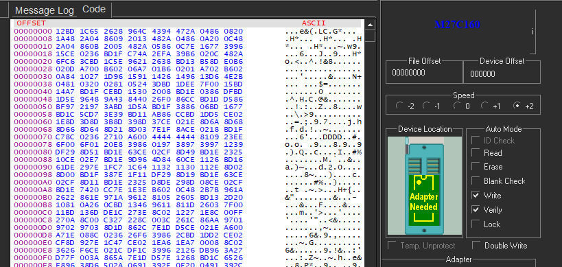
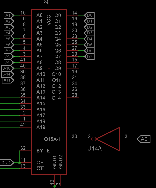
I have not purchased the adapter or tried burning 27c160 yet. Just looking to cover my bases so I know what I am getting into. Attached is how I wired up the M27C160 in the project I am working on. I am going to use a dip switch to bank select the large ROM.
Image Insert:
55765 bytes
Image Insert:
45376 bytes |
|
| Reply #1
ByteFight
11 Posts |
Posted - 11/09/2018 : 09:27:03
|
I think "Endian" is the term I want. to be more clear...
burning an 16bit ROM with 8bit data binary file for use in 8bit mode... Do I need to adjust my binary file or the GQ4X software when burning the M27C160? The datasheet is a bit cryptic about how 8 bit data mode works and no mention of burning differences for 8bit mode.... so I think i am OK as long as I make the Q15-A1 = lower most address and then all address is AX+1.
I purchased the ADP-054 and some M27C160 yesterday. It might be a couple weeks before I get PCBs made. If no one comments I will report back with my findings.
|
Edited by - ByteFight on 11/09/2018 09:29:40 |
 |
|
| Reply #2
anniel

2540 Posts |
Posted - 11/09/2018 : 12:15:07
|
quote:
Originally posted by ByteFight
I think "Endian" is the term I want. to be more clear...
burning an 16bit ROM with 8bit data binary file for use in 8bit mode... Do I need to adjust my binary file or the GQ4X software when burning the M27C160? The datasheet is a bit cryptic about how 8 bit data mode works and no mention of burning differences for 8bit mode.... so I think i am OK as long as I make the Q15-A1 = lower most address and then all address is AX+1.
I purchased the ADP-054 and some M27C160 yesterday. It might be a couple weeks before I get PCBs made. If no one comments I will report back with my findings.
Yes you need to manipulate your binary file with a good HEX editor to get the results you need. Burning will be in 16bit mode anyway. |
|
|
| Reply #3
ByteFight
11 Posts |
Posted - 11/09/2018 : 18:57:51
|
anniel, thank you for the response.
I am familiar with hex editors but I am not sure how to adjust my 8bit binary file for the 27c160. Can you tell me what type of changes I need to make or point me into the direction where I can study up on this.
|
|
|
| Reply #4
ByteFight
11 Posts |
Posted - 11/10/2018 : 06:57:33
|
Also instead of modifying the binary file is there anything I can do to the PCB? Is the issue that makes me have to edit the binary file because of Q15-A1 pin? If I invert that pin does it help?
Example
Image Insert:
22759 bytes |
Edited by - ByteFight on 11/10/2018 06:59:16 |
|
|
| Reply #5
anniel
2540 Posts |
Posted - 11/10/2018 : 15:22:02
|
quote:
Originally posted by ByteFight
Also instead of modifying the binary file is there anything I can do to the PCB? Is the issue that makes me have to edit the binary file because of Q15-A1 pin? If I invert that pin does it help?
Example
Image Insert:
22759 bytes
The Q15A�1 pin only serves to select the lower or upper part of the chip. Same as a CS if you had 2 chips if it can help you understand. Inverting it will only swap the 2. |
|
|
| Reply #6
ByteFight
11 Posts |
Posted - 11/11/2018 : 13:09:28
|
So my mistake is making the Q15-A1 the lowest most address bit (A0)? It is actually the Upper most address in byte mode.... effectively A20? ?
Trying to wrap my brain around this statement in the datasheet.
"When the BYTEVPP pin is at VIL the Byte-wide organisation is selected and the Q15A�1 pin is used for
the Address Input A�1. When the memory is logically regarded as 16 bit wide, but read in
the Byte-wide organisation, then with A�1 at VIL the lower 8 bits of the 16 bit data are
selected and with A�1 at VIH the upper 8 bits of the 16 bit data are selected."
|
|
|
| Reply #7
anniel
2540 Posts |
Posted - 11/11/2018 : 13:25:27
|
quote:
Originally posted by ByteFight
So my mistake is making the Q15-A1 the lowest most address bit (A0)? It is actually the Upper most address in byte mode.... effectively A20? ?
Trying to wrap my brain around this statement in the datasheet.
"When the BYTEVPP pin is at VIL the Byte-wide organisation is selected and the Q15A�1 pin is used for
the Address Input A�1. When the memory is logically regarded as 16 bit wide, but read in
the Byte-wide organisation, then with A�1 at VIL the lower 8 bits of the 16 bit data are
selected and with A�1 at VIH the upper 8 bits of the 16 bit data are selected."
Right and if you look closely at the datasheet you will also notice that Q15-A1 is much slower than the address lines. |
|
|
| Reply #8
ByteFight
11 Posts |
Posted - 11/26/2018 : 10:56:43
|
Ok had PCBs made and figured this out. The statement above about The Q15A-1 being the highest address bit is wrong.
When the M27C160 is set for 8 bit mode the Q15A-1 (Address MINUS one) becomes the lowest most address bit, basically A0 to the CPU chip.
When burning to the M27C160 with 8 bit data you do not need to invert A0 like shown in my picture. If the low most bit is inverted i think the byteswap button in the GQ4X software will fix it. |
|
|
| Reply #9
anniel
2540 Posts |
Posted - 11/28/2018 : 04:41:23
|
quote:
Originally posted by ByteFight
Ok had PCBs made and figured this out. The statement above about The Q15A-1 being the highest address bit is wrong.
When the M27C160 is set for 8 bit mode the Q15A-1 (Address MINUS one) becomes the lowest most address bit, basically A0 to the CPU chip.
When burning to the M27C160 with 8 bit data you do not need to invert A0 like shown in my picture. If the low most bit is inverted i think the byteswap button in the GQ4X software will fix it.
No it is not highest nor does it replace A0.
If you treat Q15A-1 as a regular address line you severely limit the speed. |
|
|
| Reply #10
ByteFight
11 Posts |
Posted - 12/16/2018 : 06:35:23
|
I have a real hardware board working. Q15A-1 gets connected to cpu A0. All other address bits are AX + 1. The A-1 is A negative 1 not a dash is what i think.
I just load my 8bit binary file in the gq4x software like normal, burn, and it works fine.
Where in the datasheet does it say The A-1 pin is super slow in 8bit mode? I read through it front and back. Unless it is something ambiguous in the ac waveform charts I don't see it.
Bonus question.... any OTP, EEPROM, etc... M27C160 alternatives with the same dip42 pin out and 8bit mode that the GQ4X can handle? Looks like MX29F1615 is the same pin out but not listed on GQ4X software. MX29F1615 needs Vpp 10v. |
Edited by - ByteFight on 12/16/2018 07:31:17 |
|
|
| |
Topic |
|