| Author |
 Topic Topic  |
|
|
Riceboy891

2 Posts |
 Posted - 07/11/2005 : 16:11:42 Posted - 07/11/2005 : 16:11:42

|
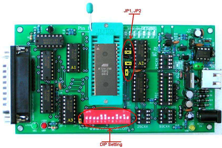
| I am really new to this so no super fancy language. I am trying to burn an at29c256 it is reading but that is it. If I id it without the 3-31 jumper it shows[---] for the chip but with the jumper it shows SST/Sanyo. Either way when i hit program it says error write sector 0. When i do a blank test is says device is not empty even though it is a new chip.($000000) Then i try to erase it and the progress bar pops up for a second then goes away and at the bottom it says erase completed by check DQ7. Please help me! |
|
| Reply #1
Riceboy891
2 Posts |
Posted - 07/11/2005 : 16:14:13
|
| oh and i cant get the led's to move so i cant get to the at29 led |
 |
|
| Reply #2
usb

138 Posts |
Posted - 07/12/2005 : 10:23:56
|
I believe your programmer is an Enhanced Willem programmer.
So, you need remove the safty jumper and set the LED to At29 position.
You do not need short the pin 3 - 31. That is for Willem 3.1 hardware. |
|
|
| Reply #3
sdezego

USA
11 Posts |
Posted - 07/21/2005 : 07:55:58
|
I was having the exact same issues using the dual power. I fought with it for a long time. After hours of researching (knowing it had to be a stupid user error on my part)I found the solution on a website outlining HowTo.
Intuitively, one would think that pin 1 from the AT29c256 would match up with what shows as pin one on the PCB, but that does not appear to be the case. If you look at the graphic diagram in the programmer software closely (Easy to see now), you will see that the chip goes in to the back of the ZIF. So, Pin 1 on the chip will actually be plugged into socket 3 of the ZIF. ZIF Socket Pins 1,2 and 31,32 will be empty.
Shawn
 |
Edited by - sdezego on 07/21/2005 07:58:54 |
|
|
| Reply #4
usb
138 Posts |
Posted - 07/21/2005 : 10:43:07
|
The pin 1 on the PCB is the 32 pin ZIF indication. Due to the different packaging chips are supported by this programmer, so, every chip's location in the ZIF may be different.
When the chip been selected form the software, the chip's location will be showed in the software.
All chip's location in the ZIF should follow the "Bottom Aligned" rule. That's means the chip need to "top-up" and the bottom need to be aligned with ZIF's bottom. |
|
|
| |
Topic |
|