| Author |
 Topic Topic  |
|
|
vertigosystems

USA
4 Posts |
 Posted - 05/16/2019 : 08:48:22 Posted - 05/16/2019 : 08:48:22


|
This is on the GQ-4x4
This also seems to apply to the 64mbit one in SOIC16 format as well.
Using ADP-098 as instructed doesn't fix the problem, I had to create my own adapter to go directly to the 40 pin ZIF.
Even though you choose the SOIC16 format, the programmer uses the SOIC8 pin format.
SOIC16 is:
IO3 --- CLK
VCC --- IO0
RST --- NC
NC --- NC
NC --- NC
NC --- NC
CS --- GND
IO1 --- IO2
The adapter I needed to rig together takes the top and bottom two pins on each side of the 16 pin package and put them in the 8 pin configuration per the datasheet.
Otherwise, you get an unidentified (FFFFFFFF) chip and it doesn't function for read or write. Once wired as:
CS --- VCC
IO1 --- IO3
IO2 --- CLK
GND --- IO0
It functions normally. Although it doesn't seem to support dual or quad reading mode
Shouldn't the programmer be using the 16 pin format when you explicitly select SOIC16 from the device list?
Is there someway to update the pin configuration on the device list, or is that locked away in the program? The devices.txt doesn't seem to give any indication of pinout.
|
Vertigo Systems LLC - Technically, the Best! |
Edited by - vertigosystems on 05/16/2019 08:48:47
|
|
| Reply #1
anniel
2597 Posts |
Posted - 05/16/2019 : 16:58:15
|
quote:
Originally posted by vertigosystems
This is on the GQ-4x4
This also seems to apply to the 64mbit one in SOIC16 format as well.
Using ADP-098 as instructed doesn't fix the problem, I had to create my own adapter to go directly to the 40 pin ZIF.
Even though you choose the SOIC16 format, the programmer uses the SOIC8 pin format.
SOIC16 is:
IO3 --- CLK
VCC --- IO0
RST --- NC
NC --- NC
NC --- NC
NC --- NC
CS --- GND
IO1 --- IO2
The adapter I needed to rig together takes the top and bottom two pins on each side of the 16 pin package and put them in the 8 pin configuration per the datasheet.
Otherwise, you get an unidentified (FFFFFFFF) chip and it doesn't function for read or write. Once wired as:
CS --- VCC
IO1 --- IO3
IO2 --- CLK
GND --- IO0
It functions normally. Although it doesn't seem to support dual or quad reading mode
Shouldn't the programmer be using the 16 pin format when you explicitly select SOIC16 from the device list?
Is there someway to update the pin configuration on the device list, or is that locked away in the program? The devices.txt doesn't seem to give any indication of pinout.
Thank you! Excellent contribution to the community.
There is some DIP settings to change some pin configurations but I think the sufficient options needs to be set in the device class. |
 |
|
| Reply #2
laptech

United Kingdom
58 Posts |
Posted - 05/17/2019 : 01:00:35
|
If you look at the data sheet of the IC, you will notice the SOIC-16 version of the chip only uses 8 of it's pins to program it.. Therefore what the company has done is made an adapter so that the 8 used pins of the SOIC-16 chip correspond to the pin out of it's WSON-8 counterpart, hence the requirement of ADP-98. If your chip is not being detected then there is a fault with your ADP-98.
The device 'Class' defines the pin-out the programmer uses. |
Laptronics UK LTd. Specialist motherboard repair. |
|
|
| Reply #3
anniel
2597 Posts |
Posted - 05/17/2019 : 02:37:37
|
quote:
Originally posted by laptech
If you look at the data sheet of the IC, you will notice the SOIC-16 version of the chip only uses 8 of it's pins to program it.. Therefore what the company has done is made an adapter so that the 8 used pins of the SOIC-16 chip correspond to the pin out of it's WSON-8 counterpart, hence the requirement of ADP-98. If your chip is not being detected then there is a fault with your ADP-98.
The device 'Class' defines the pin-out the programmer uses.
Correct and the adapter can easily be tested with an ohmmeter or the hardware test function of the software. |
|
|
| Reply #4
vertigosystems
USA
4 Posts |
Posted - 05/17/2019 : 08:49:43
|
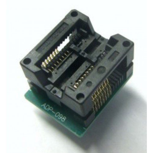
Looking at the ADP-098, it has 16 pins and a straight pin configuration where each pin 1-8 on each side correspond to the same (side and pin number) on the ZIF, so unless there are multiple versions of the 98 I don't see how this could operate as expected.
The pin configuration needed to use the 16 as an 8 was this:
Image Insert:
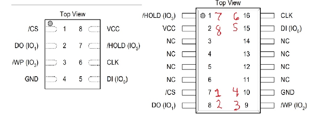
75930 bytes
But my ADP-098 is just wired as a basically mechanical socket type change with no pin reassignments. in other words, it has a SOIC16 socket on top and 16 pins on the bottom for the ZIF, rather than 8 pins on the bottom with the assignments above.
I'll admit it's possible I might have knockoff adapters since the GQ was purchased from amazon as a bundle (but it was registered successfully and authenticates as genuine)
You mentioned a different class for the devices file, is it possible to make the adapter I have work for this without doing any jumpering of wires?
|
Vertigo Systems LLC - Technically, the Best! |
|
|
| Reply #5
anniel
2597 Posts |
Posted - 05/17/2019 : 09:11:42
|
quote:
Originally posted by vertigosystems
Looking at the ADP-098, it has 16 pins and a straight pin configuration where each pin 1-8 on each side correspond to the same (side and pin number) on the ZIF, so unless there are multiple versions of the 98 I don't see how this could operate as expected.
The pin configuration needed to use the 16 as an 8 was this:
Image Insert:
75930 bytes
But my ADP-098 is just wired as a basically mechanical socket type change with no pin reassignments. in other words, it has a SOIC16 socket on top and 16 pins on the bottom for the ZIF, rather than 8 pins on the bottom with the assignments above.
I'll admit it's possible I might have knockoff adapters since the GQ was purchased from amazon as a bundle (but it was registered successfully and authenticates as genuine)
You mentioned a different class for the devices file, is it possible to make the adapter I have work for this without doing any jumpering of wires?
Does it look like this?
 |
|
|
| Reply #6
vertigosystems
USA
4 Posts |
Posted - 05/17/2019 : 15:37:32
|
Yes, that is the same adapter, but there's no special or relocating traces on the pcb. The way it looks on top is the same way it looks on the bottom.
Testing the continuity from pin to pin shows it's 1:1 from socket to pin. |
Vertigo Systems LLC - Technically, the Best! |
|
|
| |
Topic |
|